Algebraische und polynomische Beschreibung
Inhaltsverzeichnis
- 1 Aufteilung der Generatormatrix in Teilmatrizen
- 2 Generatormatrix eines Faltungscodierers mit Gedächtnis m
- 3 Generatormatrix für Faltungscodierer der Rate 1/n
- 4 GF(2)–Beschreibungsformen eines Digitalen Filters
- 5 GF(2)–Beschreibungsformen eines Digitalen Filters (2)
- 6 Anwendung der D–Transformation auf Rate–1/n–Faltungscoder (1)
- 7 Anwendung der D–Transformation auf Rate–1/n–Faltungscoder (2)
- 8 Übertragungsfunktionsmatrix – Transfer Function Matrix (1)
- 9 Übertragungsfunktionsmatrix – Transfer Function Matrix (2)
- 10 Systematische Faltungscodes (1)
- 11 Systematische Faltungscodes (2)
- 12 Filterstruktur bei gebrochen–rationaler Übertragungsfunktion
- 13 Aufgaben
Aufteilung der Generatormatrix in Teilmatrizen
Entsprechend den Ausführungen im früheren Abschnitt Lineare Codes und zyklische Codes lässt sich das Codewort $\underline{x}$ eines linearen Blockcodes aus dem Informationswort $\underline{u}$ und der Generatormatrix $\mathbf{G}$ in einfacher Weise ermitteln: $\underline{x} = \underline{u} \cdot { \boldsymbol{\rm G}}$. Dabei gilt:
- Die Vektoren $\underline{u}$ und $\underline{x}$ haben die Länge $k$ (Bitanzahl eines Informationswortes) bzw. $n$ (Bitanzahl eines Codewortes) und $\mathbf{G}$ besitzt die Dimension $k × n$ ($k$ Zeilen und $n$ Spalten).
- Bei Faltungscodierung bezeichnen dagegen $\underline{u}$ und $\underline{x}$ Sequenzen mit $k\hspace{0.05cm}' → ∞$ und $n\hspace{0.05cm}' → ∞$. Deshalb wird auch die Generatormatrix $\mathbf{G}$ in beiden Richtungen unendlich weit ausgedehnt sein.
Als Vorbereitung für die Einführung der Generatormatrix $\mathbf{G}$ auf der nächsten Seite definieren wir $m + 1$ Teilmatrizen, jeweils mit $k$ Zeilen und $n$ Spalten, die wir mit $\mathbf{G}_l$ bezeichnen, wobei $0 ≤ l ≤ m$ gilt.
$\text{Definition:}$ Wir betrachten die Teilmatrix $\mathbf{G}_l$. Diese beschreibt folgenden Sachverhalt: Ist das Matrixelement $\mathbf{G}_l(\kappa, j) = 1$, so sagt dies aus, dass das Codebit $x_i^{(j)}$ durch das Informationsbit $u_{i-l}^{(\kappa)}$ beeinflusst wird. Andernfalls ist dieses Matrixelement gleich $0$.
Diese Definition wird nun an einem Beispiel verdeutlicht.
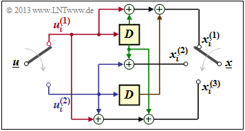
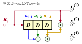
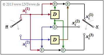
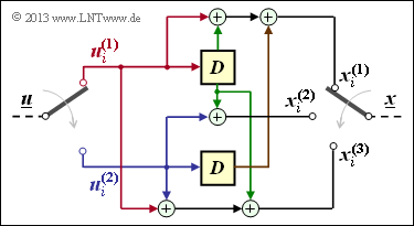
$\text{Beispiel 1:}$ Wir betrachten wiederum den Faltungscodierer gemäß nebenstehender Grafik mit den folgenden Codebits:
- \[x_i^{(1)} = u_{i}^{(1)} + u_{i-1}^{(1)}+ u_{i-1}^{(2)} \hspace{0.05cm},\]
- \[x_i^{(2)} = u_{i}^{(2)} + u_{i-1}^{(1)} \hspace{0.05cm},\]
- \[x_i^{(3)} = u_{i}^{(1)} + u_{i}^{(2)}+ u_{i-1}^{(1)} \hspace{0.05cm}.\]
Wegen der Gedächtnisordnung $m = 1$ wird dieser Codierer durch die beiden Teilmatrizen $\mathbf{G}_0$ und $\mathbf{G}_1$ vollständig charakterisiert:
- \[{ \boldsymbol{\rm G} }_0 = \begin{pmatrix} 1 & 0 & 1\\ 0 & 1 & 1 \end{pmatrix} \hspace{0.05cm}, \hspace{0.5cm} { \boldsymbol{\rm G} }_1 = \begin{pmatrix} 1 & 1 & 1\\ 1 & 0 & 0 \end{pmatrix}\hspace{0.05cm}.\]
Diese Matrizen sind wie folgt zu interpretieren:
- Erste Zeile von $\mathbf{G}_0$, rote Pfeile: $\hspace{1.1cm}u_i^{(1)}$ beeinflusst sowohl $x_i^{(1)}$ als auch $x_i^{(3)}$, nicht jedoch $x_i^{(2)}$.
- Zweite Zeile von $\mathbf{G}_0$, blaue Pfeile: $\hspace{0.6cm}u_i^{(2)}$ beeinflusst $x_i^{(2)}$ und $x_i^{(3)}$, aber nicht $x_i^{(1)}$.
- Erste Zeile von $\mathbf{G}_1$, grüne Pfeile: $\hspace{0.9cm}u_{i-1}^{(1)}$ beeinflusst alle drei Coderausgänge.
- Zweite Zeile von $\mathbf{G}_1$, brauner Pfeil: $\hspace{0.45cm}u_{i-1}^{(2)}$ beeinflusst nur $x_i^{(1)}$.
Generatormatrix eines Faltungscodierers mit Gedächtnis m
Mit den Teilmatrizen $\mathbf{G}_0, \ ... \ , \mathbf{G}_m$ lassen sich die $n$ Codebits zum Zeitpunkt $i$ wie folgt ausdrücken:
- \[\underline{x}_i = \sum_{l = 0}^{m} \hspace{0.15cm}\underline{u}_{i-l} \cdot { \boldsymbol{\rm G}}_l = \underline{u}_{i} \cdot { \boldsymbol{\rm G}}_0 + \underline{u}_{i-1} \cdot { \boldsymbol{\rm G}}_1 +\text{...} + \underline{u}_{i-m} \cdot { \boldsymbol{\rm G}}_m \hspace{0.05cm}.\]
Hierbei sind folgende vektorielle Größen zu berücksichtigen:
- \[\underline{\it u}_i = \left ( u_i^{(1)}, u_i^{(2)}, \hspace{0.05cm}... \hspace{0.1cm}, u_i^{(k)}\right )\hspace{0.05cm},\hspace{0.5cm} \underline{\it x}_i = \left ( x_i^{(1)}, x_i^{(2)}, \hspace{0.05cm}\text{...} \hspace{0.1cm}, x_i^{(n)}\right )\hspace{0.05cm}.\]
Betrachtet man die bei $i = 1$ beginnenden und sich zeitlich bis ins Unendliche erstreckenden Sequenzen
- \[\underline{\it u} = \big( \underline{\it u}_1\hspace{0.05cm}, \underline{\it u}_2\hspace{0.05cm}, \hspace{0.05cm}\text{...} \hspace{0.1cm}, \underline{\it u}_i\hspace{0.05cm}, \hspace{0.05cm}\text{...} \hspace{0.1cm} \big)\hspace{0.05cm},\hspace{0.5cm} \underline{\it x} = \big( \underline{\it x}_1\hspace{0.05cm}, \underline{\it x}_2\hspace{0.05cm}, \hspace{0.05cm}\text{...} \hspace{0.1cm}, \underline{\it x}_i\hspace{0.05cm}, \hspace{0.05cm}... \hspace{0.1cm} \big)\hspace{0.05cm},\]
so kann dieser Zusammenhang durch die Matrixgleichung $\underline{x} = \underline{u} \cdot \mathbf{G}$ ausgedrückt werden. Hierbei ist für die Generatormatrix $\mathbf{G}$ zu setzen:
- \[{ \boldsymbol{\rm G}}=\begin{pmatrix} { \boldsymbol{\rm G}}_0 & { \boldsymbol{\rm G}}_1 & { \boldsymbol{\rm G}}_2 & \cdots & { \boldsymbol{\rm G}}_m & & & \\ & { \boldsymbol{\rm G}}_0 & { \boldsymbol{\rm G}}_1 & { \boldsymbol{\rm G}}_2 & \cdots & { \boldsymbol{\rm G}}_m & &\\ & & { \boldsymbol{\rm G}}_0 & { \boldsymbol{\rm G}}_1 & { \boldsymbol{\rm G}}_2 & \cdots & { \boldsymbol{\rm G}}_m &\\ & & & \cdots & \cdots & & & \cdots \end{pmatrix}\hspace{0.05cm}.\]
Aus der Gleichung erkennt man sofort das Gedächtnis $m$ des Faltungscodes. Die Parameter $k$ und $n$ sind direkt nicht ablesbar. Sie sind aber durch die Zeilen– und Spaltenanzahl der Teilmatrizen $\mathbf{G}_l$ festgelegt.
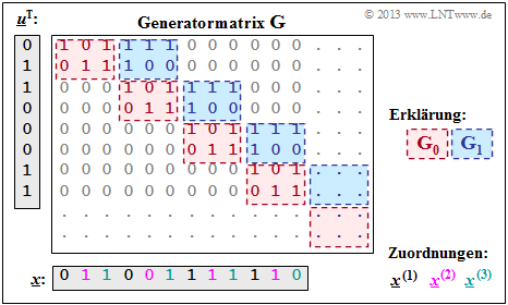
$\text{Beispiel 2:}$ Mit den zwei Matrizen $\mathbf{G}_0$ und $\mathbf{G}_1$ – siehe Beispiel 1 – erhält man die rechts skizzierte Matrix $\mathbf{G}$.
Anzumerken ist:
- Die Generatormatrix $\mathbf{G}$ erstreckt sich nach unten und nach rechts eigentlich bis ins Unendliche. Explizit dargestellt sind aber nur acht Zeilen und zwölf Spalten.
- Für die zeitlich begrenzte Informationssequenz $\underline{u} = (0, 1, 1, 0, 0, 0, 1, 1)$ ist der gezeichnete Matrixteil ausreichend. Die Codesequenz lautet dann: $\underline{x} = (0, 1, 1, 0, 0, 1, 1, 1, 1, 1, 1, 0)$.
Anhand der Beschriftungsfarben lassen sich die $n = 3$ Codewortstränge ablesen. Das gleiche Ergebnis haben wir (auf anderem Wege) im Beispiel 4 am Ende des letzten Kapitels erhalten:
- $$\underline{\it x}^{(1)} = (0\hspace{0.05cm}, 0\hspace{0.05cm}, 1\hspace{0.05cm}, 1) \hspace{0.05cm},\hspace{0.5cm} \underline{\it x}^{(2)} = (1\hspace{0.05cm}, 0\hspace{0.05cm},1\hspace{0.05cm}, 1) \hspace{0.05cm},\hspace{0.5cm} \underline{\it x}^{(3)} = (1\hspace{0.05cm}, 1\hspace{0.05cm}, 1\hspace{0.05cm}, 0) \hspace{0.05cm}.$$
Generatormatrix für Faltungscodierer der Rate 1/n
Wir betrachten nun den Sonderfall $k = 1$, zum einen aus Gründen einer möglichst einfachen Darstellung, aber auch, weil Faltungscodierer der Rate $1/n$ für die Praxis eine große Bedeutung besitzen.
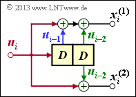
Faltungscodierer mit $k = 1, n = 2, m = 1$
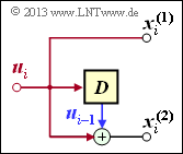
Aus der nebenstehenden Skizze kann abgeleitet werden:
- \[{ \boldsymbol{\rm G}}_0=\begin{pmatrix} 1 & 1 \end{pmatrix}\hspace{0.05cm},\hspace{0.3cm} { \boldsymbol{\rm G}}_1=\begin{pmatrix} 0 & 1 \end{pmatrix}\hspace{0.3cm} \Rightarrow \hspace{0.3cm} { \boldsymbol{\rm G}}=\begin{pmatrix} 11 & 01 & 00 & 00 & 00 & \cdots & \\ 00 & 11 & 01 & 00 & 00 & \cdots & \\ 00 & 00 & 11 & 01 & 00 & \cdots & \\ 00 & 00 & 00 & 11 & 01 & \cdots & \\ \cdots & \cdots & \cdots & \cdots & \cdots & \cdots \end{pmatrix}\hspace{0.05cm}.\]
Für die Eingangssequenz $\underline{u} = (1, 0, 1, 1)$ beginnt die Codesequenz mit $\underline{x} = (1, 1, 0, 1, 1, 1, 1, 0, \ \text{...})$. Dieses Ergebnis ist gleich der Summe der Zeilen 1, 3 und 4 der Generatormatrix.
Faltungscodierer mit $k = 1, n = 2, m = 2$
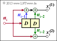
Aufgrund der Gedächtnisordnung $m = 2$ gibt es hier drei Teilmatrizen:
- \[{ \boldsymbol{\rm G}}_0=\begin{pmatrix} 1 & 1 \end{pmatrix}\hspace{0.05cm},\hspace{0.3cm} { \boldsymbol{\rm G}}_1=\begin{pmatrix} 1 & 0 \end{pmatrix}\hspace{0.05cm},\hspace{0.3cm} { \boldsymbol{\rm G}}_2=\begin{pmatrix} 1 & 1 \end{pmatrix}\]
Damit lautet die resultierende Generatormatrix:
- \[ { \boldsymbol{\rm G}}=\begin{pmatrix} 11 & 10 & 11 & 00 & 00 & 00 & \cdots & \\ 00 & 11 & 10 & 11 & 00 & 00 & \cdots & \\ 00 & 00 & 11 & 10 & 11 & 00 & \cdots & \\ 00 & 00 & 00 & 11 & 10 & 11 & \cdots & \\ \cdots & \cdots & \cdots & \cdots & \cdots & \cdots \end{pmatrix}\hspace{0.05cm}.\]
Hier führt die Eingangsssequenz $\underline{u} = (1, 0, 1, 1)$ zur Codesequenz $\underline{x} = (1, 1, 1, 0, 0, 0, 0, 1, \ \text{...})$.
Faltungscodierer mit $k = 1, n = 3, m = 3$
Wegen $m = 3$ gibt es nun vier Teilmatrizen der jeweiligen Dimension $1 × 3$:
- \[{ \boldsymbol{\rm G}}_0=\begin{pmatrix} 1 & 1 & 0 \end{pmatrix}\hspace{0.05cm},\hspace{0.3cm} { \boldsymbol{\rm G}}_1=\begin{pmatrix} 0 & 0 & 1 \end{pmatrix}\hspace{0.05cm},\hspace{0.3cm} { \boldsymbol{\rm G}}_2=\begin{pmatrix} 0 & 0 & 1 \end{pmatrix}\hspace{0.05cm},\hspace{0.3cm} { \boldsymbol{\rm G}}_3=\begin{pmatrix} 0 & 1 & 1 \end{pmatrix}\hspace{0.05cm}.\]
Damit lautet die resultierende Generatormatrix:
- \[{ \boldsymbol{\rm G}}=\begin{pmatrix} 110 & 001 & 001 & 011 & 000 & 000 & 000 & \cdots & \\ 000 & 110 & 001 & 001 & 011 & 000 & 000 & \cdots & \\ 000 & 000 & 110 & 001 & 001 & 011 & 000 & \cdots & \\ 000 & 000 & 000 & 110 & 001 & 001 & 011 & \cdots & \\ \cdots & \cdots & \cdots & \cdots & \cdots & \cdots & \cdots & \cdots \end{pmatrix}\hspace{0.05cm},\]
und man erhält für $\underline{u} = (1, 0, 1, 1)$ die Codesequenz $\underline{x} = (1, 1, 0, 0, 0, 1, 1, 1, 1, 1, 0, 0, \ \text{...})$.
GF(2)–Beschreibungsformen eines Digitalen Filters
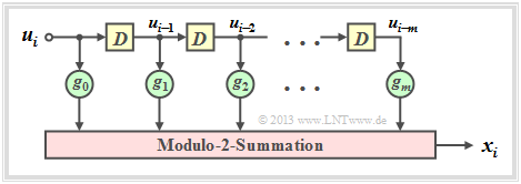
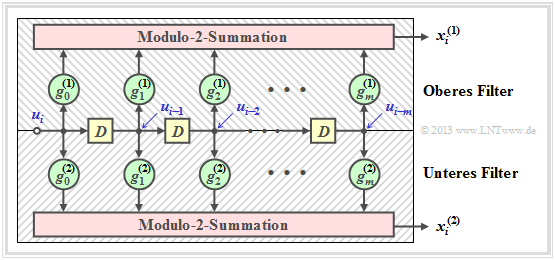
Im Kapitel Grundlagen der Faltungscodierung wurde bereits darauf hingewiesen, dass ein Faltungscodierer der Rate $1/n$ durch mehrere Digitale Filter realisiert werden kann, wobei die Filter parallel mit der gleichen Eingangsfolge $\underline{u}$ arbeiten. Bevor wir diese Aussage vertiefen, sollen zuerst die Eigenschaften eines Digitalfilters für das Galoisfeld ${\rm GF(2)}$ genannt werden.
Die Grafik ist wie folgt zu interpretieren:
- Das Filter besitzt die Impulsantwort $\underline{g} = (g_0, g_1, g_2, \ \text{...} \ , g_m)$, wobei für alle Filterkoeffizienten (mit den Indizes $0 ≤ l ≤ m$) gilt: $g_l ∈ {\rm GF}(2) = \{0, 1\}$.
- Die einzelnen Symbole $u_i$ der Eingangsfolge $\underline{u}$ seien ebenfalls binär: $u_i ∈ \{0, 1\}$. Damit gilt für das Ausgangssymbol zu den Zeitpunkten $i ≥ 1$ mit Addition und Multiplikation in ${\rm GF(2)}$:
- \[x_i = \sum_{l = 0}^{m} g_l \cdot u_{i-l} \hspace{0.05cm}.\]
- Dies entspricht der (zeitdiskreten) Faltungsoperation (englisch: Convolution), gekennzeichnet durch einen Stern. Damit kann für die gesamte Ausgangssequenz geschrieben werden:
- \[\underline{x} = \underline{u} * \underline{g}\hspace{0.05cm}.\]
- Wesentlicher Unterschied gegenüber dem Kapitel Digitale Filter im Buch „Stochastische Signaltheorie” ist die Modulo–2–Addition $(1 + 1 = 0)$ anstelle der herkömmlichen Addition $(1 + 1 = 2)$.
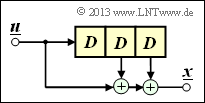
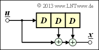
$\text{Beispiel 3:}$
Die Impulsantwort des dargestellten Digitalen Filters der Ordnung 3 lautet $\underline{g} = (1, 0, 1, 1)$.
Die Eingangssequenz dieses Filters sei zeitlich unbegrenzt: $\underline{u} = (1, 1, 0, 0, 0, \ \text{ ...})$.
Damit ergibt sich die (unendliche) Ausgangssequenz $\underline{x}$ im binären Galoisfeld ⇒ ${\rm GF(2)}$:
- \[\underline{x} = (\hspace{0.05cm}1,\hspace{0.05cm} 1,\hspace{0.05cm} 0,\hspace{0.05cm} 0,\hspace{0.05cm} 0, \hspace{0.05cm} \text{ ...} \hspace{0.05cm}) * (\hspace{0.05cm}1,\hspace{0.05cm} 0,\hspace{0.05cm} 1,\hspace{0.05cm} 1\hspace{0.05cm})\]
\[\Rightarrow \hspace{0.3cm} \underline{x} =(\hspace{0.05cm}1,\hspace{0.05cm} 0,\hspace{0.05cm} 1,\hspace{0.05cm} 1,\hspace{0.05cm} 0, \hspace{0.05cm}0,\hspace{0.05cm} \text{ ...} \hspace{0.05cm}) \oplus (\hspace{0.05cm}0,\hspace{0.05cm}\hspace{0.05cm}1,\hspace{0.05cm} 0,\hspace{0.05cm} 1,\hspace{0.05cm} 1,\hspace{0.05cm}0, \hspace{0.05cm} \hspace{0.05cm} \text{ ...}\hspace{0.05cm}) = (\hspace{0.05cm}1,\hspace{0.05cm}\hspace{0.05cm}1,\hspace{0.05cm} 1,\hspace{0.05cm} 0,\hspace{0.05cm} 1,\hspace{0.05cm} 0, \hspace{0.05cm} \text{ ...} \hspace{0.05cm}) \hspace{0.05cm}.\]
Bei der herkömmlichen Faltung (für reelle Zahlen) hätte dagegen das Ergebnis gelautet:
- \[\underline{x}= (\hspace{0.05cm}1,\hspace{0.05cm}\hspace{0.05cm}1,\hspace{0.05cm} 1,\hspace{0.05cm} 2,\hspace{0.05cm} 1,\hspace{0.05cm} 0, \text{ ...} \hspace{0.05cm}) \hspace{0.05cm}.\]
GF(2)–Beschreibungsformen eines Digitalen Filters (2)
Zeitdiskrete Signale kann man auch durch Polynome bezüglich einer Dummy–Variablen repräsentieren.
\[X(D) = x_0 + x_1 \cdot D + x_2 \cdot D^2 + \hspace{0.05cm}...\hspace{0.05cm}= \sum_{i = 0}^{\infty} x_i \cdot D^i \hspace{0.05cm}.\]
Für diese spezielle Transformation in einen Bildbereich verwenden wir auch die Notation:
\[\underline{x} = (x_0, x_1, x_2,\hspace{0.05cm}...\hspace{0.05cm}) \quad \circ\!\!-\!\!\!-^{\hspace{-0.25cm}D}\!\!\!-\!\!\bullet\quad X(D) = \sum_{i = 0}^{\infty} x_i \cdot D^i \hspace{0.05cm}.\]
In der Literatur wird manchmal $x(D)$ anstelle von $X(D)$ verwendet. Wir schreiben in LNTwww aber alle Bildbereichsfunktionen mit Großbuchstaben, zum Beispiel Fourier–, Laplace– und $D$–Transformation:
\[x(t) \hspace{0.15cm} \circ\!\!-\!\!\!-^{\hspace{-0.25cm}}\!\!\!-\!\!\bullet\hspace{0.15cm} X(f)\hspace{0.05cm},\hspace{0.4cm} x(t) \hspace{0.15cm} \circ\!\!-\!\!\!-^{\hspace{-0.25cm}\rm L}\!\!\!-\!\!\bullet\hspace{0.15cm} X(p) \hspace{0.05cm},\hspace{0.4cm} \underline{x} \hspace{0.15cm} \circ\!\!-\!\!\!-^{\hspace{-0.25cm}D}\!\!\!-\!\!\bullet\hspace{0.15cm} X(D) \hspace{0.05cm}.\]
Wir wenden nun die $D$–Transformation auch auf die Informationssequenz $\underline{u}$ und die Impulsantwort $\underline{g}$ an. Aufgrund der zeitlichen Begrenzung von $\underline{g}$ ergibt sich die obere Summationsgrenze bei $G(D)$ zu $i = m$:
\[\underline{u} = (u_0, u_1, u_2,\hspace{0.05cm}...\hspace{0.05cm}) \quad \circ\!\!-\!\!\!-^{\hspace{-0.25cm}D}\!\!\!-\!\!\bullet\quad U(D) = \sum_{i = 0}^{\infty} u_i \cdot D^i \hspace{0.05cm},\]
\[\underline{g} = (g_0, g_1, \hspace{0.05cm}...\hspace{0.05cm}, g_m) \quad
\circ\!\!-\!\!\!-^{\hspace{-0.25cm}D}\!\!\!-\!\!\bullet\quad
G(D) = \sum_{i = 0}^{m} g_i \cdot D^i \hspace{0.05cm}.\]
\[\underline{x} = \underline{u} * \underline{g} \quad \circ\!\!-\!\!\!-^{\hspace{-0.25cm}D}\!\!\!-\!\!\bullet\quad X(D) = U(D) \cdot G(D) \hspace{0.05cm}.\]
Man bezeichnet, wie in der Systemtheorie allgemein üblich, auch die $D$–Transformierte $G(D)$ der Impulsantwort $\underline{g}$ als Übertragungsfunktion (englisch: Transfer Function).
Der (recht einfache) Beweis dieses wichtigen Ergebnisses finden Sie in der Angabe zu Aufgabe Z3.3.
\[\underline{u} = (\hspace{0.05cm}1\hspace{0.05cm},\hspace{0.05cm} 1\hspace{0.05cm},\hspace{0.05cm} 0\hspace{0.05cm},\hspace{0.05cm} 0\hspace{0.05cm},\hspace{0.05cm}...\hspace{0.05cm}) \quad \circ\!\!-\!\!\!-^{\hspace{-0.25cm}D}\!\!\!-\!\!\bullet\quad U(D) = 1+ D \hspace{0.05cm},\]
\[\underline{g} = (\hspace{0.05cm}1\hspace{0.05cm},\hspace{0.05cm} 0\hspace{0.05cm},\hspace{0.05cm} 1\hspace{0.05cm},\hspace{0.05cm} 1\hspace{0.05cm}) \quad \circ\!\!-\!\!\!-^{\hspace{-0.25cm}D}\!\!\!-\!\!\bullet\quad G(D) = 1+ D^2 + D^3 \hspace{0.05cm}.\]
Wie im letzten Beispiel erhält man auch auf diesem Lösungsweg:
\[X(D) \hspace{-0.15cm} = \hspace{-0.15cm} U(D) \cdot G(D) = (1+D) \cdot (1+ D^2 + D^3) =\] \[\hspace{1cm} = \hspace{-0.15cm} 1+ D^2 + D^3 +D + D^3 + D^4 = 1+ D + D^2 + D^4 \]
\[\Rightarrow \hspace{0.4cm} \underline{x} = (\hspace{0.05cm}1\hspace{0.05cm},\hspace{0.05cm} 1\hspace{0.05cm},\hspace{0.05cm} 1\hspace{0.05cm},\hspace{0.05cm} 0\hspace{0.05cm},\hspace{0.05cm} 1\hspace{0.05cm},\hspace{0.05cm} 0\hspace{0.05cm}, ... \hspace{0.05cm}) \hspace{0.05cm}.\]
Die Multiplikation mit $D$ im Bildbereich entspricht im Zeitbereich einer Verschiebung um eine Stelle nach rechts, weshalb man $D$ als Verzögerungsoperator (englisch: Delay Operator) bezeichnet:
\[W(D) = D \cdot X(D) \quad \bullet\!\!-\!\!\!-^{\hspace{-0.25cm}D}\!\!\!-\!\!\circ\quad \underline{w} = (\hspace{0.05cm}0\hspace{0.05cm},\hspace{0.05cm}1\hspace{0.05cm},\hspace{0.05cm} 1\hspace{0.05cm},\hspace{0.05cm} 1\hspace{0.05cm},\hspace{0.05cm} 0\hspace{0.05cm},\hspace{0.05cm} 1\hspace{0.05cm},\hspace{0.05cm} 0\hspace{0.05cm}, ... \hspace{0.05cm}) \hspace{0.05cm}.\]
Anwendung der D–Transformation auf Rate–1/n–Faltungscoder (1)
Wir wenden nun die Ergebnisse der letzten Seite auf einen Faltungscoder an, wobei wir uns zunächst auf den Sonderfall $k = 1$ beschränken. Ein solcher $(n, \ k = 1)$–Faltungscode lässt sich mit $n$ Digitalen Filtern realisieren, die auf der gleichen Informationssequenz $\underline{u}$ parallel arbeiten. Die Grafik zeigt die Anordnung für den Codeparameter $n = 2$ ⇒ Coderate $R = 1/2$.
Die nachfolgenden Gleichungen gelten für beide Filter gleichermaßen, wobei für das obere Filter $j = 1$ und für das untere Filter $j = 2$ zu setzen ist:
- Die Impulsantworten der beiden Filter ergeben sich zu
- \[\underline{g}^{(j)} = (g_0^{(j)}, g_1^{(j)}, \hspace{0.05cm}...\hspace{0.05cm}, g_m^{(j)}\hspace{0.01cm}) \hspace{0.05cm},\hspace{0.2cm}{\rm mit }\hspace{0.15cm} j \in \{1,2\}\hspace{0.05cm}.\]
- Die beiden Ausgangssequenzen lauten:
- \[\underline{x}^{(j)} = (x_0^{(j)}, x_1^{(j)}, x_2^{(j)}, \hspace{0.05cm}...\hspace{0.05cm}) = \underline{u} \cdot \underline{g}^{(j)} \hspace{0.05cm},\hspace{0.2cm}{\rm mit }\hspace{0.15cm} j \in \{1,2\}\hspace{0.05cm}.\]
- Hierbei ist berücksichtigt, dass das obere Filter und das untere Filter beide auf der gleichen Eingangssequenz $\underline{u} = (u_0, u_1, u_2, \ ...)$ arbeiten.
- Für die $D$–Transformierten der Ausgangssequenzen gilt:
- \[X^{(j)}(D) = U(D) \cdot G^{(j)}(D) \hspace{0.05cm},\hspace{0.2cm}{\rm mit }\hspace{0.15cm} j \in \{1,2\}\hspace{0.05cm}.\]
Auf der nächsten Seite verwenden wir eine kompaktere Schreibweise.
Anwendung der D–Transformation auf Rate–1/n–Faltungscoder (2)
Um den soeben dargelegten Sachverhalt kompakter darstellen zu können, definieren wir nun folgende vektorielle Größen eines Faltungscodes der Rate $1/n$:
\[\underline{G}(D) = \left ( G^{(1)}(D), G^{(2)}(D), \hspace{0.05cm}...\hspace{0.1cm}, G^{(n)} (D) \right )\hspace{0.05cm}.\]
Der Vektor $\underline{X}(D)$ beinhaltet die $D$–Transformierten der $n$ Codesequenzen $\underline{x}^{(1)}, \underline{x}^{(2)}, \ ... \ , \underline{x}^{(n)}$:
\[\underline{X}(D) = \left ( X^{(1)}(D), X^{(2)}(D), \hspace{0.05cm}...\hspace{0.1cm}, X^{(n)} (D) \right )\hspace{0.05cm}.\]
Damit erhält man die folgende Vektorgleichung:
\[\underline{X}(D) = U(D) \cdot \underline{G}(D)\hspace{0.05cm}.\]
Aufgrund des Codeparameters $k = 1$ ist $U(D)$ hier keine vektorielle Größe.
\[\underline{g}^{(1)} \hspace{-0.15cm} = \hspace{-0.15cm} (\hspace{0.05cm}1\hspace{0.05cm},\hspace{0.05cm} 1\hspace{0.05cm},\hspace{0.05cm} 1\hspace{0.05cm}) \quad \circ\!\!-\!\!\!-^{\hspace{-0.25cm}D}\!\!\!-\!\!\bullet\quad G(D) = 1+ D + D^2 \hspace{0.05cm},\] \[\underline{g}^{(2)} \hspace{-0.15cm} = \hspace{-0.15cm} (\hspace{0.05cm}1\hspace{0.05cm},\hspace{0.05cm} 0\hspace{0.05cm},\hspace{0.05cm} 1\hspace{0.05cm}) \quad \circ\!\!-\!\!\!-^{\hspace{-0.25cm}D}\!\!\!-\!\!\bullet\quad G(D) = 1+ D^2 \]
\[\Rightarrow \hspace{0.3cm} \underline{G}(D) = \big ( 1+ D + D^2 \hspace{0.05cm}, \hspace{0.1cm}1+ D^2 \big )\hspace{0.05cm}.\]
Die Informationssequenz sei $\underline{u} = (1, 0, 1, 1)$, was zur $D$–Transformierten $U(D) = 1 + D^2 + D^3$ führt. Damit erhält man
\[\underline{X}(D) = \left ( X^{(1)}(D),\hspace{0.1cm} X^{(2)}(D) \right ) = U(D) \cdot \underline{G}(D) \hspace{0.05cm}, \hspace{0.2cm}\]
wobei
\[{X}^{(1)}(D) \hspace{-0.15cm} = \hspace{-0.15cm} (1+ D^2 + D^3) \cdot (1+ D + D^2)=\] \[\hspace{1.5cm} = \hspace{-0.15cm}1+ D + D^2 + D^2 + D^3 + D^4 + D^3 + D^4 + D^5 = 1+ D + D^5\]
\[\Rightarrow \underline{x}^{(1)} = (\hspace{0.05cm}1\hspace{0.05cm},\hspace{0.05cm}1\hspace{0.05cm},\hspace{0.05cm} 0\hspace{0.05cm},\hspace{0.05cm} 0\hspace{0.05cm},\hspace{0.05cm} 0\hspace{0.05cm},\hspace{0.05cm} 1\hspace{0.05cm},\hspace{0.05cm} 0\hspace{0.05cm}, \hspace{0.05cm} 0\hspace{0.05cm}, \hspace{0.05cm} ... \hspace{0.05cm} \hspace{0.05cm}) \hspace{0.05cm},\]
\[{X}^{(2)}(D) \hspace{-0.15cm} = \hspace{-0.15cm} (1+ D^2 + D^3) \cdot (1+ D^2)=\] \[\hspace{1.5cm} = \hspace{-0.15cm}1+ D^2 + D^2 + D^4 + D^3 + D^5 = 1+ D^3 + D^4 + D^5\]
\[\Rightarrow \underline{x}^{(2)} = (\hspace{0.05cm}1\hspace{0.05cm},\hspace{0.05cm}0\hspace{0.05cm},\hspace{0.05cm} 0\hspace{0.05cm},\hspace{0.05cm} 1\hspace{0.05cm},\hspace{0.05cm} 1\hspace{0.05cm},\hspace{0.05cm} 1\hspace{0.05cm},\hspace{0.05cm} 0\hspace{0.05cm}, \hspace{0.05cm} 0\hspace{0.05cm}, \hspace{0.05cm} ... \hspace{0.05cm} \hspace{0.05cm}) \hspace{0.05cm}.\]
Das gleiche Ergebnis haben wir in der Aufgabe Z3.1 auf anderem Wege erhalten. Nach dem Multplexen der beiden Sränge erhält man wieder: $\underline{x} = (11, 10, 00, 01, 01, 11, 00, 00, \ ...)$.
Übertragungsfunktionsmatrix – Transfer Function Matrix (1)
Auf der letzten Seite haben wir gesehen, dass ein Faltungscode der Rate $1/n$ sich am kompaktesten als Vektorgleichung im $D$–transformierten Bereich beschreiben lässt:
\[\underline{X}(D) = U(D) \cdot \underline{G}(D)\hspace{0.05cm}.\]
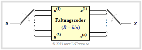
Nun erweitern wir das Resultat auf Faltungscodierer mit mehr als einem Eingang ⇒ $k ≥ 2$ (siehe Grafik).
Um einen Faltungscode der Rate $k/n$ im $D$–Bereich abbilden zu können, muss die Dimension obiger Vektorgleichung hinsichtlich Eingang und Übertragungsfunktion erhöht werden:
\[\underline{X}(D) = \underline{U}(D) \cdot { \boldsymbol{\rm G}}(D)\hspace{0.05cm},\]
mit folgenden Maßnahmen:
- Aus der skalaren Funktion $U(D)$ wird der Vektor $\underline{U}(D) = (U^{(1)}(D), \ U^{(2)}(D), \ ... \ , \ U^{(k)}(D))$.
- Aus dem Vektor $\underline{G}(D)$ wird die $k × n$–Matrix $\mathbf{G}(D)$, die man als Übertragungsfunktionsmatrix bezeichnet (englisch: Transfer Function Matrix oder auch Polynomial Generator Matrix):
- \[{\boldsymbol{\rm G}}(D)=\begin{pmatrix} G_1^{(1)}(D) & G_1^{(2)}(D) & \ldots & G_1^{(n)}(D)\\ G_2^{(1)}(D) & G_2^{(2)}(D) & \ldots & G_2^{(n)}(D)\\ \vdots & \vdots & & \vdots\\ G_k^{(1)}(D) & G_k^{(2)}(D) & \ldots & G_k^{(n)}(D) \end{pmatrix}\hspace{0.05cm}.\]
- Jedes der $k \cdot n$ Matrixelemente $G_i^{(j)}(D)$ mit $1 ≤ i ≤ k, 1 ≤ j ≤ n$ ist ein Polynom über der Dummy–Variablen $D$ im Galoisfeld ${\rm GF}(2)$, maximal vom Grad $m$, wobei $m$ das Gedächtnis angibt.
- Für die obige Übertragungsfunktionsmatrix kann mit den zu Beginn dieses Kapitels definierten Teilmatrizen $\mathbf{G}_0, \ ... \ , \mathbf{G}_m$ auch geschrieben werden (als Index verwenden wir wieder $l$):
- \[{\boldsymbol{\rm G}}(D) = \sum_{l = 0}^{m} {\boldsymbol{\rm G}}_l \cdot D\hspace{0.03cm}^l = {\boldsymbol{\rm G}}_0 + {\boldsymbol{\rm G}}_1 \cdot D + {\boldsymbol{\rm G}}_2 \cdot D^2 + ... \hspace{0.05cm}+ {\boldsymbol{\rm G}}_m \cdot D\hspace{0.03cm}^m \hspace{0.05cm}.\]
Auf der nächsten Seite werden diese Definitionen und Gesetzmäßigkeiten an einem ausführlichen Beispiel verdeutlicht.
Übertragungsfunktionsmatrix – Transfer Function Matrix (2)
\[{ \boldsymbol{\rm G}}_0 = \begin{pmatrix} 1 & 0 & 1\\ 0 & 1 & 1 \end{pmatrix} \hspace{0.05cm}, \\ { \boldsymbol{\rm G}}_1 = \begin{pmatrix} 1 & 1 & 1\\ 1 & 0 & 0 \end{pmatrix}\hspace{0.05cm}.\]
Wegen $m = 1$ existieren keine Teilmatrizen für $l ≥ 2$. Damit lautet die Übertragungsfunktionsmatrix:
\[{\boldsymbol{\rm G}}(D) = {\boldsymbol{\rm G}}_0 + {\boldsymbol{\rm G}}_1 \cdot D = \begin{pmatrix} 1+D & D & 1+D\\ D & 1 & 1 \end{pmatrix} \hspace{0.05cm}.\]
Die (zeitlich begrenzte) Informationssequenz sei $\underline{u} = (0, 1, 1, 0, 0, 0, 1, 1)$, woraus sich die beiden Eingangsfolgen wie folgt ergeben:
\[\underline{u}^{(1)} \hspace{-0.15cm} = \hspace{-0.15cm} (\hspace{0.05cm}0\hspace{0.05cm},\hspace{0.05cm}1\hspace{0.05cm},\hspace{0.05cm} 0\hspace{0.05cm},\hspace{0.05cm} 1\hspace{0.05cm}) \quad \circ\!\!-\!\!\!-^{\hspace{-0.25cm}D}\!\!\!-\!\!\bullet\quad {U}^{(1)}(D) = D + D^3 \hspace{0.05cm},\] \[\underline{u}^{(2)} \hspace{-0.15cm} = \hspace{-0.15cm} (\hspace{0.05cm}1\hspace{0.05cm},\hspace{0.05cm}0\hspace{0.05cm},\hspace{0.05cm} 0\hspace{0.05cm},\hspace{0.05cm} 1\hspace{0.05cm}) \quad \circ\!\!-\!\!\!-^{\hspace{-0.25cm}D}\!\!\!-\!\!\bullet\quad {U}^{(2)}(D) = 1 + D^3 \hspace{0.05cm}.\]
Daraus folgt für den Vektor der $D$–Transformierten am Coderausgang:
\[\underline{X}(D) \hspace{-0.15cm} = \hspace{-0.15cm} \big (\hspace{0.05cm} {X}^{(1)}(D)\hspace{0.05cm}, \hspace{0.05cm} {X}^{(2)}(D)\hspace{0.05cm}, \hspace{0.05cm} {X}^{(3)}(D)\hspace{0.05cm}\big ) = \underline{U}(D) \cdot {\boldsymbol{\rm G}}(D)\] \[\hspace{1cm} = \hspace{-0.15cm} \begin{pmatrix} D+D^3 & 1+D^3 \end{pmatrix} \cdot \begin{pmatrix} 1+D & D & 1+D\\ D & 1 & 1 \end{pmatrix}\hspace{0.05cm}.\]
Damit ergeben sich in den drei Strängen folgende Codesquenzen:
\[{X}^{(1)}(D) \hspace{-0.15cm} = \hspace{-0.15cm} (D + D^3) \cdot (1+D) + (1 + D^3) \cdot D =\] \[\hspace{1.5cm} = \hspace{-0.15cm} D + D^2 + D^3 + D^4 + D + D^4 = D^2 + D^3\]
\[\Rightarrow \underline{x}^{(1)} = (\hspace{0.05cm}0\hspace{0.05cm},\hspace{0.05cm}0\hspace{0.05cm},\hspace{0.05cm} 1\hspace{0.05cm},\hspace{0.05cm} 1\hspace{0.05cm},\hspace{0.05cm}\hspace{0.05cm} 0\hspace{0.05cm},\hspace{0.05cm}\hspace{0.05cm} 0\hspace{0.05cm},\hspace{0.05cm} ... \hspace{0.05cm}) \hspace{0.05cm},\]
\[{X}^{(2)}(D) \hspace{-0.15cm} = \hspace{-0.15cm} (D + D^3) \cdot D + (1 + D^3) \cdot 1 =\] \[\hspace{1.5cm} = \hspace{-0.15cm} D^2 + D^4 + 1 + D^3 = 1+D^2 + D^3 + D^4\]
\[\Rightarrow \underline{x}^{(2)} = (\hspace{0.05cm}1\hspace{0.05cm},\hspace{0.05cm}0\hspace{0.05cm},\hspace{0.05cm} 1\hspace{0.05cm},\hspace{0.05cm} 1\hspace{0.05cm},\hspace{0.05cm} 1\hspace{0.05cm},\hspace{0.05cm}\hspace{0.05cm} 0\hspace{0.05cm},\hspace{0.05cm}\hspace{0.05cm} ... \hspace{0.05cm}) \hspace{0.05cm},\]
\[{X}^{(3)}(D) \hspace{-0.15cm} = \hspace{-0.15cm} (D + D^3) \cdot (1 + D) + (1 + D^3) \cdot 1 =\] \[\hspace{1.5cm} = \hspace{-0.15cm} D + D^2 + D^3+ D^4 + 1 + D^3 = 1+ D + D^2 + D^4\]
\[\Rightarrow \underline{x}^{(3)} = (\hspace{0.05cm}1\hspace{0.05cm},\hspace{0.05cm}1\hspace{0.05cm},\hspace{0.05cm} 1\hspace{0.05cm},\hspace{0.05cm} 0\hspace{0.05cm},\hspace{0.05cm} 1\hspace{0.05cm},\hspace{0.05cm}\hspace{0.05cm} 0\hspace{0.05cm},\hspace{0.05cm}\hspace{0.05cm} ... \hspace{0.05cm}) \hspace{0.05cm}.\]
Die gleichen Ergebnisse haben wir auf anderen Wegen bereits in vorherigen Beispielen erhalten:
- im Beispiel von Kapitel 3.1, Seite 4.
- im Beispiel von Kapitel 3.2, Seite 2.
Systematische Faltungscodes (1)
Die Polynomrepräsentation anhand der Übertragungsfunktionsmtrix $\mathbf{G}(D)$ ermöglicht Einblicke in die Struktur eines Faltungscodes. Beispielsweise erkennt man anhand dieser $k × n$–Matrix, ob es sich um einen systematischen Code handelt. Darunter versteht man einen Code, bei dem die Codesequenzen $\underline{x}^{(1)}, \ ... \ , \ \underline{x}^{(k)}$ mit den Informationssequenzen $\underline{u}^{(1)}, \ ... \ , \ \underline{u}^{(k)}$ identisch sind. Die Grafik zeigt beispielhaft einen systematischen $(n = 4, k = 3)$–Faltungscode.
Ein systematischer $(n, k)$–Faltungscode liegt immer dann vor, wenn die Übertragungsfunktionsmatrix (mit $k$ Zeilen und $n$ Spalten) folgendes Aussehen hat:
\[{\boldsymbol{\rm G}}(D) = {\boldsymbol{\rm G}}_{\rm sys}(D) = \big [ \hspace{0.05cm} {\boldsymbol{\rm I}}_k\hspace{0.05cm} ; \hspace{0.1cm} {\boldsymbol{\rm P}}(D) \hspace{0.05cm}\big ] \hspace{0.05cm}.\]
Hierbei ist folgende Nomenklatur verwendet:
- $\mathbf{I}_k$ bezeichnet eine diagonale Einheitsmatrix der Dimension $k × k$.
- $\mathbf{P}(D)$ ist eine $k × (n \, –k)$–Matrix, wobei jedes Matrixelement ein Polynom in $D$ beschreibt.
\[{\boldsymbol{\rm G}}_{\rm sys}(D) = \begin{pmatrix} 1 & 0 & 1+D^2\\ 0 & 1 & 1+D \end{pmatrix}\hspace{0.05cm}.\]
Andere systematische Faltungscodes mit gleichem $n$ und gleichem $k$ unterscheiden sich demgegenüber nur durch die beiden Matrixelemente in der letzten Spalte.
Zu jedem $(n, k)$–Faltungscode mit der Generatormatrix $\mathbf{G}(D)$ kann ein äquivalenter systematischer Code gefunden werden, dessen $D$–Matrix wir mit $\mathbf{G}_{\rm sys}(D)$ benennen.
Auf der nächsten Seite wird gezeigt, wie man von einer beliebigen Matrix $\mathbf{G}(D)$ durch Aufspalten in zwei Teilmatrizen $\mathbf{T}(D)$ und $\mathbf{Q}(D)$ und verschiedene Matrizenoperationen zur Matrix $\mathbf{G}_{\rm sys}(D)$ kommt.
Systematische Faltungscodes (2)
Um von einer Übertragungsfunktionsmatrix $\mathbf{G}(D)$ zur Matrix $\mathbf{G}_{\rm sys}(D)$ eines äquivalenten systematischen Faltungscodes zu kommen, geht man entsprechend der Grafik auf der letzten Seite wie folgt vor:
- Man unterteilt die $k × n$–Matrix $\mathbf{G}(D)$ in eine quadratische Matrix $\mathbf{T}(D)$ mit $k$ Zeilen und $k$ Spalten und bezeichnet den Rest mit $\mathbf{Q}(D)$.
- Anschließend berechnet man die zu $\mathbf{T}(D)$ inverse Matrix $\mathbf{T}^{–1}(D)$ und daraus die Matrix für den äquivanten systematischen Code:
- \[{\boldsymbol{\rm G}}_{\rm sys}(D)= {\boldsymbol{\rm T}}^{-1}(D) \cdot {\boldsymbol{\rm G}}(D) \hspace{0.05cm}.\]
- Da $\mathbf{T}^{–1}(D) \cdot \mathbf{T}(D)$ die $k × k$–Einheitsmatrix $\mathbf{I}_k$ ergibt, kann die Übertragungsfunktionsmatrix des äquivalenten systematischen Codes in der gewünschten Form geschrieben werden:
- \[{\boldsymbol{\rm G}}_{\rm sys}(D) = \big [ \hspace{0.05cm} {\boldsymbol{\rm I}}_k\hspace{0.05cm} ; \hspace{0.1cm} {\boldsymbol{\rm P}}(D) \hspace{0.05cm}\big ] \hspace{0.5cm}{\rm mit}\hspace{0.5cm} {\boldsymbol{\rm P}}(D)= {\boldsymbol{\rm T}}^{-1}(D) \cdot {\boldsymbol{\rm Q}}(D) \hspace{0.05cm}. \hspace{0.05cm}\]
Man erkennt dies aber auch anhand der Übertragungsfunktionsmatrix:
\[{\boldsymbol{\rm G}}(D) = \big [ \hspace{0.05cm} {\boldsymbol{\rm T}}(D)\hspace{0.05cm} ; \hspace{0.1cm} {\boldsymbol{\rm Q}}(D) \hspace{0.05cm}\big ]\]
\[\Rightarrow \hspace{0.3cm} {\boldsymbol{\rm T}}(D) = \begin{pmatrix} 1+D & D\\ D & 1 \end{pmatrix}\hspace{0.05cm},\hspace{0.2cm} {\boldsymbol{\rm Q}}(D) = \begin{pmatrix} 1+D \\ 1 \end{pmatrix}\hspace{0.05cm}.\]
Die Determinante von $\mathbf{T}(D)$ ergibt sich zu $(1 + D) \cdot 1 + D \cdot D = 1 + D + D^2$ und ist ungleich $0$. Somit kann für die Inverse von $\mathbf{T}(D)$ geschrieben werden (Vertauschung der Diagonalelemente!):
\[{\boldsymbol{\rm T}}^{-1}(D) = \frac{1}{1+D+D^2} \cdot \begin{pmatrix} 1 & D\\ D & 1+D \end{pmatrix}\hspace{0.05cm}.\]
Das Produkt $\mathbf{T}(D) \cdot \mathbf{T}^{–1}(D)$ ergibt die Einheitsmatrix $\mathbf{I}_2$, und für die dritte Spalte von $\mathbf{G}_{\rm sys}(D)$ gilt:
\[{\boldsymbol{\rm P}}(D)= {\boldsymbol{\rm T}}^{-1}(D) \cdot {\boldsymbol{\rm Q}}(D) = \frac{1}{1+D+D^2} \cdot \begin{pmatrix} 1 & D\\ D & 1+D \end{pmatrix}\cdot \begin{pmatrix} 1+D\\ 1 \end{pmatrix} \]
\[\Rightarrow \hspace{0.3cm} {\boldsymbol{\rm P}}(D) = \frac{1}{1+D+D^2} \cdot \begin{pmatrix} (1+D) + D \\ D \cdot (1+D) + (1+D) \end{pmatrix} = \frac{1}{1+D+D^2} \cdot \begin{pmatrix} 1 \\ 1+D^2 \end{pmatrix} \]
\[\Rightarrow \hspace{0.2cm}{\boldsymbol{\rm G}}_{\rm sys}(D) = \begin{pmatrix} 1 & 0 & \frac{1}{1+D+D^2}\\ 0 & 1 &\frac{1+D^2}{1+D+D^2} \end{pmatrix}\hspace{0.05cm}. \]
Es ist noch zu klären, wie das Filter einer solchen gebrochen–rationalen Übertragungsfunktion aussieht.
Filterstruktur bei gebrochen–rationaler Übertragungsfunktion
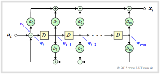
Hat eine Übertragungsfunktion die Form $G(D) = A(D)/B(D)$, so bezeichnet man das zugehörige Filter als rekursiv. Bei einem rekursiven Faltungscodierer mit dem Gedächtnis $m$ kann für die beiden Polynome $A(D)$ und $B(D)$ allgemein geschrieben werden:
\[A(D) \hspace{-0.15cm} = \hspace{-0.15cm} \sum_{l = 0}^{m} a_l \cdot D^l = a_0 + a_1 \cdot D + a_2 \cdot D^2 + ... \hspace{0.05cm} + a_m \cdot D^m \hspace{0.05cm},\] \[B(D) \hspace{-0.15cm} = \hspace{-0.15cm} 1 + \sum_{l = 1}^{m} b_l \cdot D^l = 1 + b_1 \cdot D + b_2 \cdot D^2 + ... \hspace{0.05cm} + b_m \cdot D^m \hspace{0.05cm}.\]
Die Grafik zeigt die entsprechende Filterstruktur in der so genannten Controller Canonical Form.
Die Koeffizienten $a_0, \ ... \ , \ a_m$ beschreiben den Vorwärtszweig, während $b_1, \ ... \ , \ b_m$ eine Rückkopplung bilden. Alle Koeffizienten sind binär, also $1$ (durchgehende Verbindung) oder $0$ (fehlende Verbindung).
\[x_i \hspace{-0.15cm} = \hspace{-0.15cm} w_i + w_{i-2} \hspace{0.05cm},\] \[w_i \hspace{-0.15cm} = \hspace{-0.15cm} u_i + w_{i-1}+ w_{i-2} \hspace{0.05cm}.\]
Entsprechend gilt für die $D$–Transformierten:
\[X(D) \hspace{0.15cm} = \hspace{0.15cm} W(D) + W(D) \cdot D^2 =\] \[ \hspace{1.3cm} = \hspace{0.15cm} W(D) \cdot \left ( 1+ D^2 \right ) \hspace{0.05cm},\]
\[W(D) = \hspace{0.08cm} U(D) + W(D) \cdot D+ W(D) \cdot D^2 \hspace{0.3cm}\Rightarrow \hspace{0.3cm} U(D) = W(D) \cdot \left ( 1+ D + D^2 \right ) \hspace{0.05cm}.\]
Somit erhält man für die Übertragungsfunktion dieses Filters:
\[G(D) = \frac{X(D)}{U(D)} = \frac{1+D^2}{1+D+D^2} \hspace{0.05cm}. \]
Im Beispiel zu den systematischen Faltungscodes hat sich genau ein solcher Ausdruck ergeben.
Aufgaben
A3.2 G–Matrix eines Faltungscoders
Zusatzaufgaben:3.2 (3, 1, 3)–Faltungscodierer
Zusatzaufgaben:3.3 Faltung und D–Transformation
A3.4 Systematische Faltungscodes
Zusatzaufgaben:3.4 Äquivalente Faltungscodes?
A3.5 Rekursive Filter für GF(2)
